


 Français
 2026.06.25
Deye BOS-B Pro-A3 System Architecture: How PCS, MPPT, STS and BMS Work Together
Content
- 1 One System, Four Modules — Why Architecture Matters in C&I Storage
- 2 The PCS Module: Power Conversion at the Core
- 3 The MPPT Module: Maximizing PV Yield Before It Reaches the Battery
- 4 The STS Module: Grid, Off-Grid, and Diesel in Under 10 Milliseconds
- 5 The Battery System: BOS-B Pro-A3 and Its BMS
- 6 How the Four Modules Interconnect
- 7 Protection and Reliability Features Across the System
- 8 What This Architecture Means for Project Decision-Making
One System, Four Modules — Why Architecture Matters in C&I Storage
A 2.5MW commercial energy storage system is only as reliable as the way its components talk to each other. The Deye BOS-B Pro-A3 takes a modular approach: rather than bundling all functions into a single box, it assigns each core task — power conversion, solar harvesting, grid switching, and battery management — to a dedicated module. The result is a system that can be sized from 125kW up to 2.5MW without redesigning the architecture from scratch.
This article walks through the four hardware layers of the BOS-B Pro-A3 — the PCS, MPPT, STS, and BMS — explaining what each one does, how they interconnect, and what that means for project planning and long-term operations.
The PCS Module: Power Conversion at the Core
The Power Conversion System (PCS) is the electrical heart of the BOS-B Pro-A3. Available in two ratings — 100kW (SUN-100K-PCS01HP3) and 125kW (SUN-125K-PCS01HP3) — each unit manages bidirectional energy flow between the battery bank and the AC grid. Charging draws power from the grid or PV source into the battery; discharging feeds stored energy back out to connected loads.
Key performance figures for the 125kW model: maximum AC output of 125kW, charge and discharge current up to 200A, and a peak efficiency of 98.5% (Euro efficiency: 97.8%). The DC input voltage window is 630–1000V, which aligns directly with the battery stack configurations the BOS-B Pro-A3 supports.
One design decision worth noting for procurement: the PCS integrates zero-export control and time-of-use (ToU) scheduling natively, eliminating the need for a separate energy management system (EMS) controller. This reduces both hardware cost and points of failure in the communications chain.
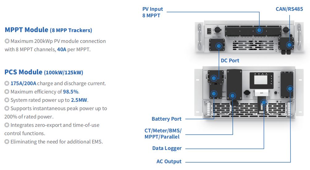
The PCS unit operates across a wide ambient temperature range (−40°C to 60°C, with derating above 45°C), carries an IP65 ingress protection rating, and uses intelligent air cooling. It supports grid connection in 3L+N+PE configuration at 220/380V or 230/400V, with grid frequency tolerance of 45–55Hz or 55–65Hz.
Scaling: From One Unit to 2.5MW
Individual PCS units can be paralleled through the STS module to reach system-level power. One 100kW PCS unit connects to up to five units per STS, while the 125kW variant supports four — giving a maximum system output of 500kW per STS module. Five STS modules in parallel bring total system capacity to 2.5MW. This stacking logic means a project can start at 125kW and expand incrementally without replacing core equipment.
The MPPT Module: Maximizing PV Yield Before It Reaches the Battery
The MPPT module (SUN-MPPT-L01-EU-AM8) sits between the PV string array and the DC bus that feeds the PCS. Its job is to extract maximum power from connected solar panels under variable irradiance conditions and deliver it as a stable DC output in the 630–1000V range.
The module supports eight independent MPP trackers, each rated at 40A input current, for a total maximum PV input capacity of 200kWp. Maximum PV input voltage is 800V; the MPPT voltage operating range is 180–750V, with full-load operation optimised in the 450–750V window. Tracker efficiency exceeds 99.9%, and overall module efficiency is above 99%.
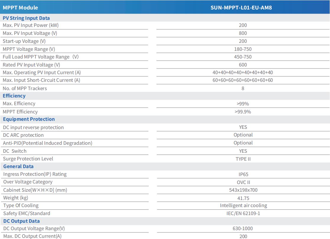
Having eight independent channels matters practically. On a commercial rooftop or ground-mount with multiple string orientations, shading profiles, or panel types, a single-tracker system would force all strings to operate at a compromise voltage. Eight separate trackers allow each string group to operate at its own optimum point, recovering yield that would otherwise be lost to mismatch losses.
The MPPT module shares the IP65 protection rating of the PCS, making the combination suitable for outdoor installation without additional enclosures. It uses intelligent air cooling and complies with IEC/EN 62109-1.
The STS Module: Grid, Off-Grid, and Diesel in Under 10 Milliseconds
The Static Transfer Switch (STS) module (SUN-STS500L) handles the connection logic between three power sources — utility grid, diesel generator, and the PCS output — and the load bus. Its defining specification is a switching time of less than 10ms, fast enough to be imperceptible to most sensitive commercial equipment.
Each of the three connection paths (GEN, Grid, Load) is electrically independent and rated at 500kW. This independence means a fault or planned disconnection on one path does not affect the others. The STS can switch seamlessly between three operating modes:
- On-grid mode: PCS operates in parallel with the utility grid, charging batteries during off-peak periods or exporting during peak periods.
- Off-grid mode: Grid connection is severed; the PCS forms a standalone AC bus to supply loads directly from battery.
- Diesel hybrid mode: A generator is brought online as the primary AC source, with the PCS providing peak shaving, smoothing, or battery top-up as needed.
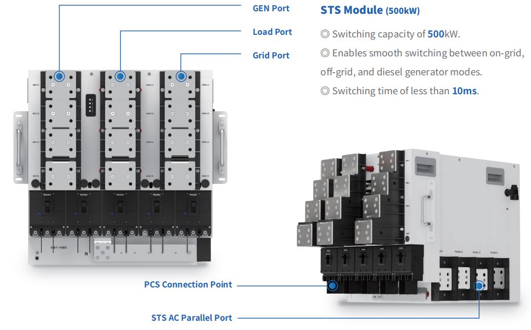
For project managers specifying sites with unreliable grid supply, this tri-mode capability means a single hardware installation can handle both routine grid-tied operation and islanded emergency backup — without switching to a different inverter platform. The STS carries an IP20 rating and an OVC III overvoltage category, appropriate for direct connection to LV distribution panels.
Connectivity Spec Summary
| Parameter | Grid / PCS Side | Load Side | GEN Side |
|---|---|---|---|
| Rated Active Power | 500kW | 500kW | 500kW |
| Rated Current | 758 / 725A | 758 / 725A | 758 / 725A |
| Rated Voltage | 220/380V or 230/400V (3-phase) | 220/380V or 230/400V (3-phase) | 220/380V or 230/400V (3-phase) |
| Grid Connection | 3L/N/PE | 3L/N/PE | 3L/N/PE |
| Frequency | 50Hz / 60Hz | 50Hz / 60Hz | 50Hz / 60Hz |
The Battery System: BOS-B Pro-A3 and Its BMS
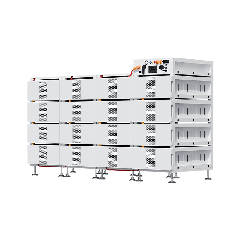
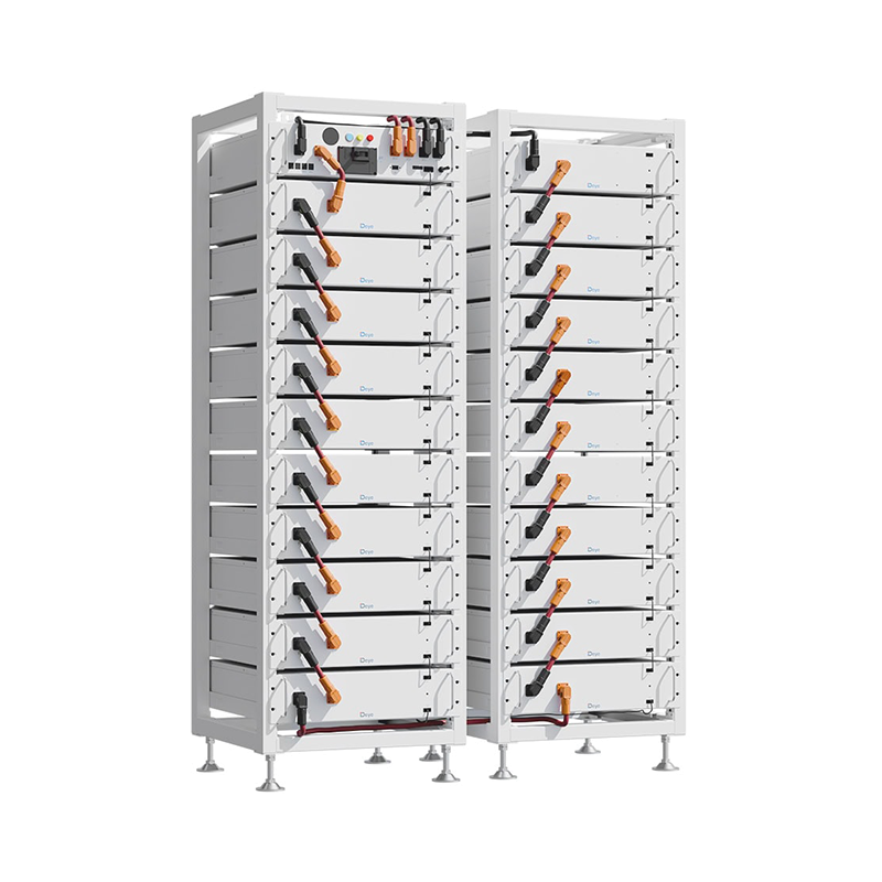
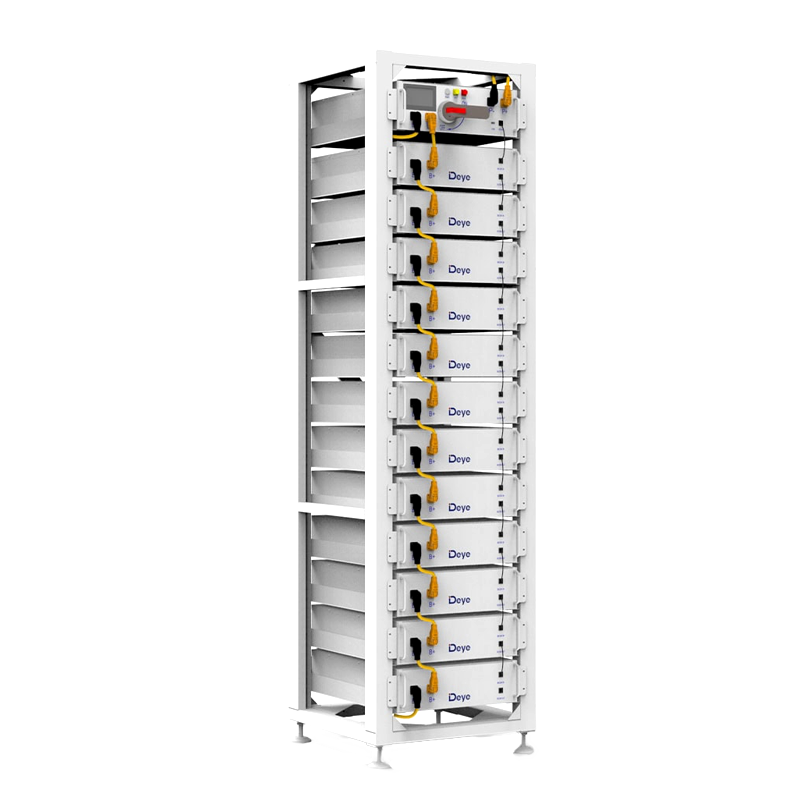
The battery racks that carry the BOS-B Pro-A3 designation use lithium iron phosphate (LFP) chemistry — a deliberate choice for commercial applications where cycle longevity and thermal stability outweigh raw energy density. Each battery module (BOS-B-Pack16-A3) holds 314Ah at 51.2V nominal, giving 16.08kWh per module.
Modules are stacked in series within a rack. The system supports between 5 and 16 modules per rack, with the 16-module configuration yielding a nominal stack voltage of 819.2V and 257.23kWh total energy per rack (231.51kWh usable at the recommended 90% depth of discharge). Maximum charge and discharge current per rack is 180A.
The Battery Management System (BMS) sits in the PDU module (BOS-B-PDU-2-A) at the top of each rack. It communicates with the PCS via CAN bus, with TCP and RS485 also available for supervisory connections. The BMS handles cell balancing, state-of-charge (SOC) estimation, fault detection, and thermal management coordination with the smart fan cooling system. An LCD display on the PDU shows real-time SOC and active fault codes without requiring a laptop or app connection.
The rated cycle life is ≥6,000 cycles to 70% end-of-life capacity at 25°C with 0.5C charge/discharge — translating to roughly 16 years of daily cycling at standard conditions. The system carries a 10-year warranty and holds CE, IEC62619, IEC62040, and UN38.3 certifications.
Battery-to-PCS Matching Rules
The number of racks per PCS unit depends on the operating mode and MPPT open-circuit voltage:
- PCS only, on-grid: 14–16 racks
- PCS only, off-grid: 15–16 racks
- PCS + MPPT, MPPT Voc ≤ 800V: 16 racks (on/off-grid)
- PCS + MPPT, MPPT Voc ≤ 750V: 15 racks (on/off-grid)
- PCS + MPPT, MPPT Voc ≤ 700V: 14 racks (on-grid only)
This matching table is the key starting point for any capacity planning exercise: PV string design and battery count are not independent decisions — they must be co-optimised against the MPPT voltage operating window.
How the Four Modules Interconnect
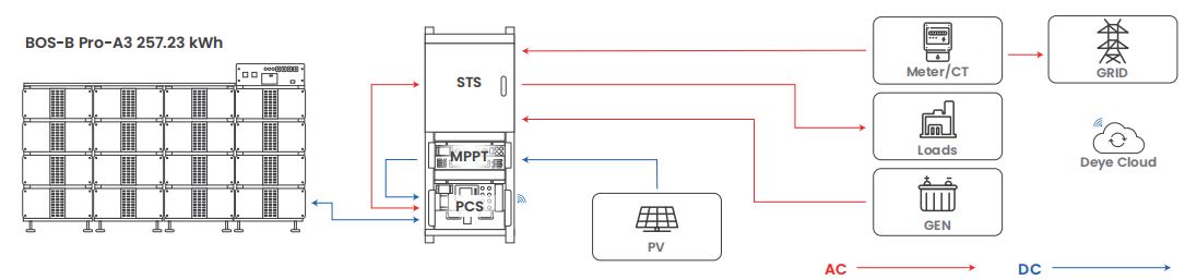
The data and power flows in the BOS-B Pro-A3 follow a clear hierarchy. On the DC side, PV strings feed into the MPPT module, which converts and stabilises their output before passing it to the PCS DC input. The battery racks connect to the PCS via high-current DC cabling (the accessory package BOS-B-AP-A includes 1AWG power cables up to 3,000mm). The BMS in each rack communicates with the PCS over CAN, enabling the PCS to adapt its charging profile dynamically to battery state — no manual parameter tuning required.
On the AC side, the PCS output connects to the STS module's PCS Connection Point. The STS then manages the relationship between that AC bus and the three external connections: utility grid, generator, and building load. A CT/meter at the grid connection point provides real-time import/export data back to the PCS for zero-export enforcement.
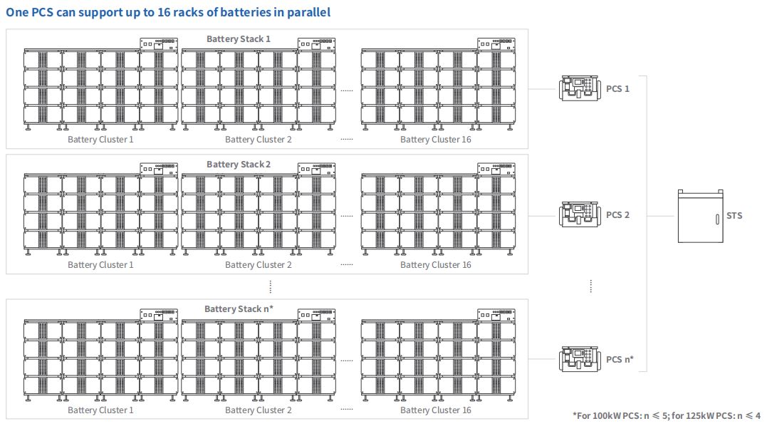
Communication between all modules runs over a combination of CAN (battery-to-PCS), RS485 (monitoring and metering), and WIFI (cloud uplink via the integrated Data Logger). The Deye Cloud platform receives this data stream and enables remote ToU scheduling, performance monitoring, and firmware updates — without requiring a site visit for routine configuration changes.
Protection and Reliability Features Across the System
Each module carries its own protection layer, and the system is designed so that a failure in one module does not cascade. The PCS includes AC output overcurrent and overvoltage protection, short-circuit protection, thermal protection, anti-islanding protection, insulation impedance detection, and residual current detection — all integrated, with no external relay panel required. Surge protection is TYPE II on both DC and AC sides.
The PCS and MPPT modules both carry IP65 protection, making them suitable for outdoor cabinet installation. The STS and BMS modules are rated IP20, intended for indoor switchroom or container deployment. Peak power support on the PCS allows 200% of rated power for up to 15 seconds, covering motor start-up loads and other short-duration demand spikes that would otherwise require oversizing the system.
At the battery level, the BMS monitors individual cell voltages and temperatures continuously, balancing charge distribution across modules and triggering protective disconnection if parameters exceed safe limits. The yellow HV indicator and red alarm indicator on the PDU provide immediate visual status without requiring any monitoring software.
What This Architecture Means for Project Decision-Making
The modular design of the BOS-B Pro-A3 has direct implications for how projects are scoped and budgeted. Because PCS units, MPPT modules, and battery racks are independently sized and added, a site can be designed for current load requirements and expanded later without replacing the STS or rewiring the AC distribution. This is a meaningful difference from integrated all-in-one systems, where capacity expansion often requires replacing the entire unit.
The integrated EMS in the PCS removes one procurement line item and one vendor relationship from the project. Zero-export and ToU logic run natively on the PCS firmware, monitored and adjusted through the Deye Cloud interface. For sites where the grid operator requires strict export limits, this native capability simplifies commissioning and compliance documentation.
The 10ms STS switching time deserves attention in load sensitivity assessments. For most commercial HVAC, lighting, and IT loads, a sub-10ms transition is invisible — no UPS bridging required for the transition itself. Projects with extremely sensitive equipment (medical imaging, precision manufacturing) should verify load tolerance independently, but for the majority of C&I applications the STS switching speed removes the need for a separate UPS layer to cover the grid-to-battery transition.
Finally, the 6,000-cycle battery specification at 90% DoD projects a useful life well beyond the standard 10-year warranty period under typical commercial cycling patterns. For procurement teams building 20-year financial models, this is a meaningful input — the battery replacement cycle is a capital cost that shifts depending on cycle depth and ambient temperature assumptions, and the BOS-B Pro-A3's LFP chemistry provides more predictable degradation curves than NMC alternatives at elevated temperatures.








3+ Branch Offices
1+ Factory
Required fields are marked


Copyright @ Hangzhou Seetek New Energy Sci-tech Co., LtD. All rights reserved Solar Energy Storage Solution Solar Energy Storage Products Supplier
