


 Français
 2026.07.14
Deye MC-L430 5-Level Safety Protection Explained: Cell to Cabinet Design
Content
- 1 Why Safety Architecture Decides Whether a C&I Battery Cabinet Survives Ten Years
- 2 Five Layers Between a Warning Sign and a Fire
- 3 Cell Fuse to PCS Contactor: How the 3+3 Electrical Protection Chain Actually Breaks a Fault
- 4 Insulation Monitoring: Catching the Faults That Never Trip a Breaker
- 5 High-Voltage Interlocking: Removing the Human Error Variable
- 6 Where Active and Passive Exhaust Fit Into Explosion Prevention
- 7 Certification as the Closing Argument
Why Safety Architecture Decides Whether a C&I Battery Cabinet Survives Ten Years
A 430kWh liquid-cooled cabinet packed with LiFePO4 cells sits at 768V DC and cycles thousands of amperes a day. That combination — high energy density, high voltage, and constant thermal load — is exactly why commercial and industrial battery buyers now scrutinize safety architecture as closely as they scrutinize round-trip efficiency. A single thermal event in a 430kWh cabinet does not just damage one asset; it can take down an entire site, trigger insurance disputes, and stall a project's return on investment for years.
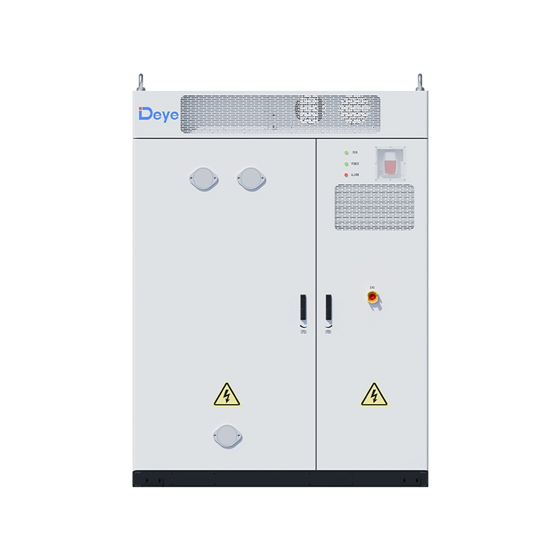
The Deye MC-L430-2H3 all-in-one C&I energy storage cabinet approaches this problem as a layered system rather than a single feature. Its safety design stacks five protection tiers on top of dual electrical fault-breaking paths, continuous insulation monitoring, and physical interlocking — each layer catching what the previous one missed. This piece walks through how those layers actually work, from the individual cell fuse up to the cabinet-level venting structure.
Five Layers Between a Warning Sign and a Fire
Most battery safety marketing collapses into a single phrase: "thermal runaway protection." The MC-L430 series breaks that phrase into five distinct, sequential functions, each with a different trigger condition and a different physical mechanism.
- Battery thermal runaway detection. Gas sensors, smoke sensors, temperature probes, and per-cell voltage monitoring run continuously across every pack, providing an early warning window of 50 minutes or more before a thermal event would otherwise become critical.
- Early warning. The system flags abnormal signatures — off-pattern gas concentration, unexpected temperature gradients — before they escalate into a runaway condition, giving operators time to isolate a cluster remotely.
- Directed exhaust. Rather than letting gases accumulate inside a sealed enclosure, the cabinet channels them along a defined path out of the cabinet, reducing the odds of a localized combustible pocket forming.
- Active venting. Once directed out, an active exhaust stage clears residual gases, cutting the risk of a delayed explosion after the initial event has already been contained.
- Fire suppression. If ignition still occurs, a combined aerosol-and-water spray system engages to stop propagation between adjacent packs.
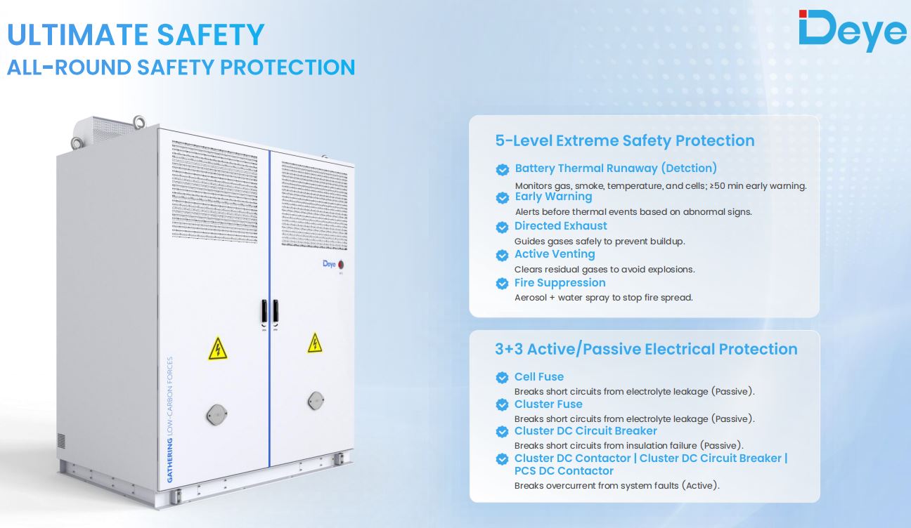
This sequencing matters because it separates prevention from containment. The first two stages exist to stop a fault before it becomes thermal; the last three exist to make sure that if prevention fails, the failure stays local. Cabinets that only advertise "fire suppression" are typically describing stage five alone — the last line of defense, not the whole system.
Cell Fuse to PCS Contactor: How the 3+3 Electrical Protection Chain Actually Breaks a Fault
Thermal protection handles heat and gas. A separate chain handles current — and it needs to, because an electrical short can develop faster than any thermal sensor can react. The MC-L430 series runs three passive protection devices and three active ones, layered so that a fault gets caught regardless of where in the circuit it originates.
| Protection Component | Type | Fault It Interrupts |
|---|---|---|
| Cell fuse | Passive | Short circuit from electrolyte leakage at cell level |
| Cluster fuse | Passive | Short circuit from electrolyte leakage at cluster level |
| Cluster DC circuit breaker | Passive | Short circuit from insulation failure |
| Cluster DC contactor | Active | Overcurrent from system-level faults |
| Cluster DC circuit breaker (active mode) | Active | Overcurrent from system-level faults |
| PCS DC contactor | Active | Overcurrent from system-level faults |
The logic behind splitting passive and active protection is straightforward once you separate the two failure modes they address. Electrolyte leakage and insulation breakdown are physical degradation events — a fuse or breaker responds to the resulting short regardless of whether the control system is even awake. System-level overcurrent, by contrast, often stems from a fault the controller can see coming — a downstream short, a charging anomaly — so an active contactor can intervene before current climbs to a level a passive fuse would need to physically melt through.
Running both in parallel means the cabinet doesn't depend on a single point of failure. If the active contactor's control logic is delayed for any reason, the passive fuses are still doing their job upstream.
Insulation Monitoring: Catching the Faults That Never Trip a Breaker
Circuit breakers and fuses respond to current. Insulation degradation, by contrast, often develops slowly and doesn't generate enough current to trip anything — until it does, usually at the worst possible moment. That's the gap insulation monitoring is built to close.
The MC-L430 platform runs two parallel monitoring functions:
- Insulation resistance detection continuously checks the DC side for insulation faults, catching gradual resistance decay in cabling or cell packaging before it becomes a full short.
- Leakage current detection monitors the AC side, flagging abnormal current paths to ground that indicate a compromised insulation barrier somewhere in the PCS or output wiring.
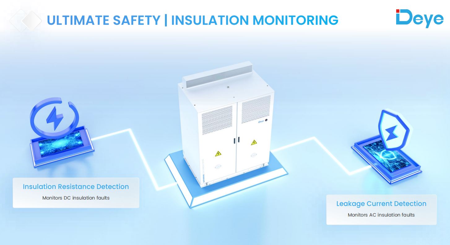
Splitting DC and AC monitoring rather than relying on a single combined sensor matters because the two sides of the system fail differently. DC insulation faults tend to originate in the battery packs or DC busbar — high-voltage, low-frequency conditions. AC leakage faults are more often wiring or PCS-output issues, closer to the grid interface. Treating them as one monitoring problem would blur the diagnostic signal operators need to locate a fault quickly during maintenance.
High-Voltage Interlocking: Removing the Human Error Variable
At 768V nominal DC (ranging up to 876V), the MC-L430's battery bus sits well above the threshold where accidental contact is genuinely dangerous, and where disconnecting a live circuit under load creates arc-flash risk on its own. High-voltage interlocking exists specifically to take that risk out of the hands of whoever is standing in front of the cabinet.
The interlock system enforces four behaviors:
- Blocks live disconnection. High-voltage circuits cannot be broken under load, eliminating the arc-flash exposure that comes from disconnecting energized DC connections.
- Displays real-time interlock status. Technicians get a clear indication of whether the system is actually safe to open, rather than relying on assumption or a general shutdown procedure.
- Requires full discharge before access. Maintenance panels physically cannot be opened until stored energy has been released, removing the possibility of contact with a charged circuit.
- Restricts access to live components. During normal operation or partial servicing, energized parts stay physically shielded from incidental contact.
This is where the design philosophy of the whole safety stack becomes visible: rather than trusting procedure and training alone, the cabinet makes the unsafe action mechanically impossible. That's a meaningfully different guarantee than a warning label or a lockout-tagout checklist, both of which depend on a human following them correctly every single time.
Where Active and Passive Exhaust Fit Into Explosion Prevention
Combustible gas doesn't need an ignition source to be dangerous — it needs concentration. That's the specific risk the cabinet's exhaust architecture is built to prevent, independent of whether a fire ever starts.
Two exhaust mechanisms work together. An active exhaust fan pulls gas out through a dedicated vent whenever the system detects a buildup condition, giving the cabinet a powered response even in still-air installation sites. A passive directed exhaust structure, built entirely from mechanical geometry rather than powered components, channels gas along a predetermined path regardless of whether the fan is running — a backup that doesn't depend on electrical power staying available during a fault.
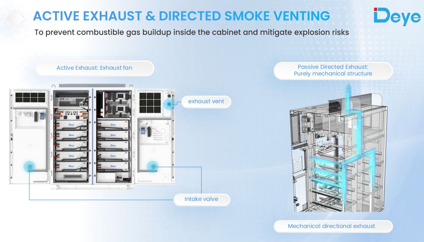
Having both matters more than it might first appear. A purely active system fails if the fault that triggers gas release also disables power to the fan. A purely passive system can't respond fast enough on its own in a large-format cabinet holding hundreds of kilowatt-hours. Combining them means the cabinet has a response even in the failure mode where its own controls are compromised.
Certification as the Closing Argument
Every layer described above is a design claim. Certification is what turns that claim into a verified one. The MC-L430 platform carries UN38.3, IEC62619, IEC62477, IEC63056, IEC60730, IEC61000, UL9540A, and IEC62933 — a set that spans transport safety, cell and battery system safety, power conversion equipment standards, and large-format energy storage fire testing specifically.
UL9540A is worth calling out separately from the rest. It's not a design standard — it's a fire propagation test protocol that evaluates whether thermal runaway in one cell actually spreads to adjacent cells, modules, and units under controlled test conditions. A cabinet passing UL9540A testing has had its containment claims verified under conditions designed to force a failure, not just documented on a datasheet.
For procurement teams evaluating cabinets side by side, this is the practical takeaway: the individual safety features matter, but the certification stack is what confirms those features perform as a system rather than as a list of isolated components. Buyers comparing options across the full range of C&I battery energy storage systems should treat the certification list as a starting filter, not an afterthought — it's the fastest way to separate genuinely tested safety architecture from marketing language.






3+ Branch Offices
1+ Factory
Required fields are marked


Copyright @ Hangzhou Seetek New Energy Sci-tech Co., LtD. All rights reserved Solar Energy Storage Solution Solar Energy Storage Products Supplier
