


 Français
 2026.07.14
Deye MS-GS215-2H3: Unifying EMS, PCS, BMS and STS in One C&I ESS
Content
- 1 Four Subsystems, One Procurement Line
- 2 All-in-One Design: EMS, PCS, and BMS on One Platform
- 3 Battery Architecture: From a 3.2V Cell to a 768V Cluster
- 4 PCS and MPPT: Where Storage Meets Solar
- 5 MS-EMS: The Coordination Layer
- 6 MS-TS500-2: The Switch That Makes On/Off-Grid Seamless
- 7 How the Four Systems Combine in the Field
- 8 What Integration Actually Buys the Project
Four Subsystems, One Procurement Line
A typical commercial and industrial storage project used to mean four separate purchase orders: a battery management system from one vendor, a power conversion system from another, an energy management platform layered on top, and a static transfer switch bolted on for backup power. Each interface between them became a point of integration risk.
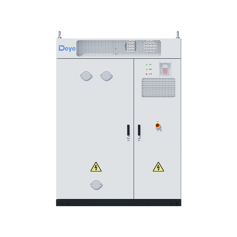
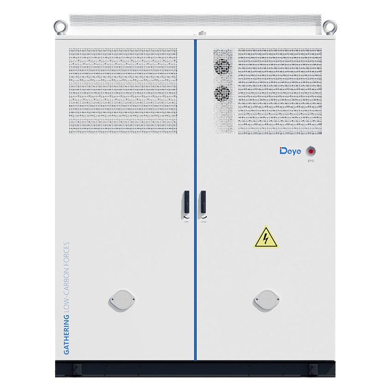
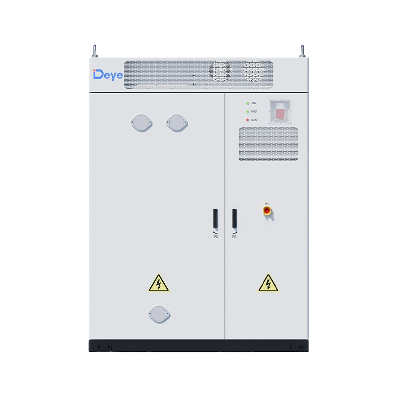
Deye's MS-GS215-2H3 collapses that stack into a single cabinet family. The battery management system (BMS), power conversion system (PCS), and energy management system (EMS) sit on one coordinated platform inside the 215 kWh unit, while the companion MS-TS500-2 static transfer switch (STS) handles grid, generator, and backup load switching in under 10 milliseconds. The rest of this article walks through how each piece is specified and how they fit together electrically.
All-in-One Design: EMS, PCS, and BMS on One Platform
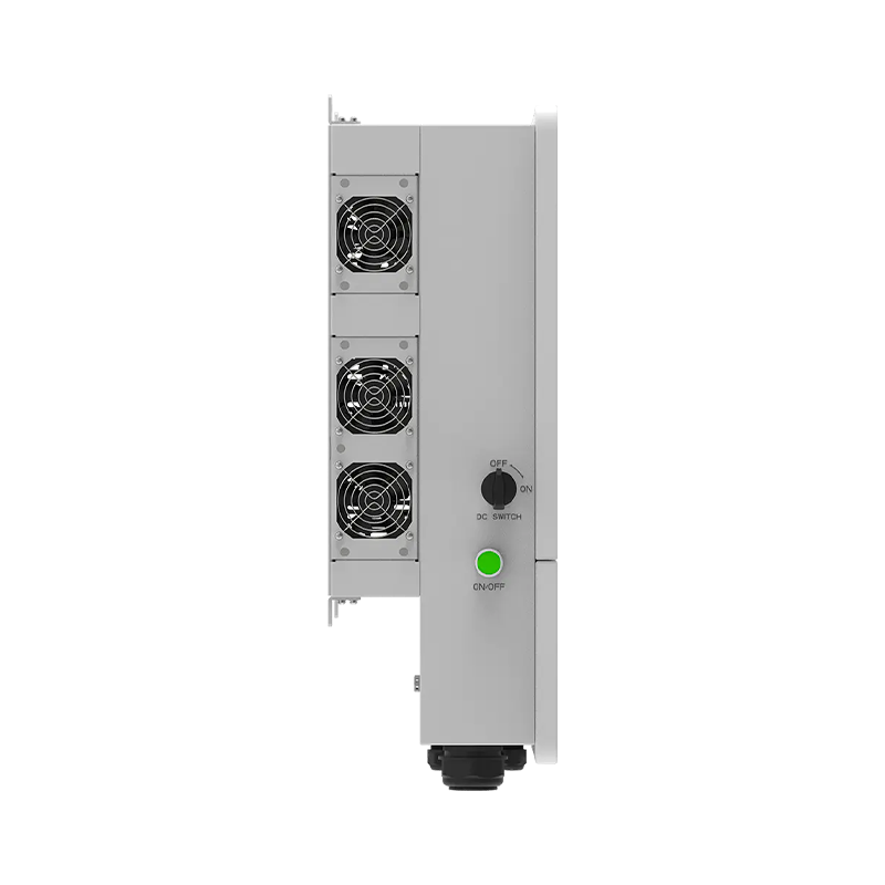
Inside the cabinet, the battery compartment, PCS/MPPT room, and fire suppression system are stacked as physically separate zones but run under one control logic. The EMS reads real-time cell data from the BMS, decides charge/discharge strategy, and issues commands directly to the PCS — there is no third-party gateway translating between systems. Full specifications for this configuration are listed on the MS-GS215-2H3 C&I energy storage system product page.
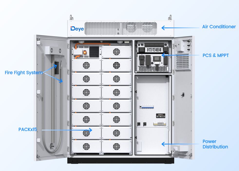
That physical integration shows up in the numbers: the cabinet's advertised ≥6,000 cycles and 70% end-of-life capacity retention are only achievable if the BMS's cell-level monitoring, the EMS's SOC balancing logic, and the PCS's charge/discharge curve are tuned to the same battery chemistry from day one — not retrofitted together after the fact.
That physical integration shows up in the numbers: the cabinet's advertised ≥6,000 cycles and 70% end-of-life capacity retention are only achievable if the BMS's cell-level monitoring, the EMS's SOC balancing logic, and the PCS's charge/discharge curve are tuned to the same battery chemistry from day one — not retrofitted together after the fact.
Battery Architecture: From a 3.2V Cell to a 768V Cluster
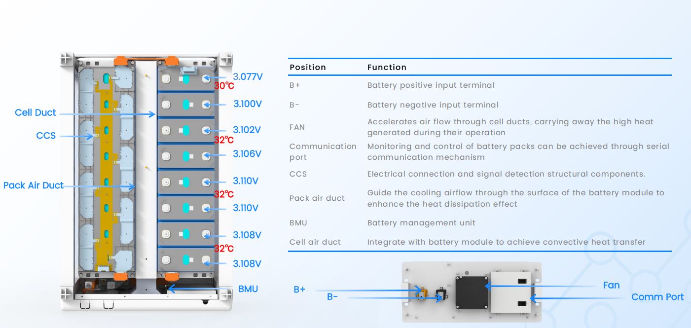
The BMS layer is built on a three-tier hierarchy — cell, pack, and cluster — each with its own monitoring point. A single LFP cell runs at 3.2V and 173.7×204.6×71.7mm; sixteen of them form a 51.2V pack; fifteen packs in series form the full 768V cluster that feeds the PCS.
| Level | Dimension (W×D×H, mm) | Weight | Voltage | Voltage Range | Capacity |
|---|---|---|---|---|---|
| Cell | 173.7 × 204.6 × 71.7 | 5.49 ± 0.3 kg | 3.2V | 2.5 ~ 3.65V | 0.896 kWh |
| Pack | 526 × 784.5 × 230 | 105 kg | 51.2V | 40 ~ 58.4V | 14.3 kWh |
| Cluster | 1865 × 1000 × 2500 | 3030 kg | 768V | 660 ~ 864V | 215 kWh |
The cluster arrangement is 1P240S — 240 cells in series, one string — giving a rated charge/discharge current of 130A and a peak of 150kW for up to 10 seconds. That peak headroom is what lets the EMS chase short demand spikes without over-provisioning the PCS.
PCS and MPPT: Where Storage Meets Solar
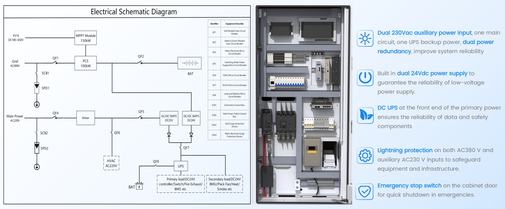
The PCS is rated at 100kW AC output (152A rated, 167A max) at 380/400Vac, 3L/N/PE, with a maximum round-trip efficiency of 97.6% and THD below 3%. Both the storage-only MS-G215-2H3 and the PV-integrated MS-GS215-2H3 share this converter core; the difference is the GS variant's built-in 200kWp MPPT stage.
| Parameter | MS-G215-2H3 | MS-GS215-2H3 |
|---|---|---|
| AC Output Power | 100 kW | 100 kW |
| Battery Operating Voltage | 660 ~ 864 Vdc | 660 ~ 864 Vdc |
| PV Input Power | — | 200 kWp |
| Number of MPPT | — | 8 channels |
| MPPT Voltage Range | — | 180 ~ 880 V |
| Max. Efficiency | 97.6% | 97.6% |
| Max. Number of Parallel (off-grid) | 10 pcs | 10 pcs |
Sizing the MPPT stage at 200kWp against a 100kW PCS output — a 2:1 DC-to-AC ratio — is a deliberate oversizing choice. It keeps the converter closer to full output in low-irradiance conditions and lets excess PV charge the battery directly through the DC bus rather than clipping.
MS-EMS: The Coordination Layer
The EMS is a standalone wall-mounted controller (488×188×588mm, ≤24.5kg) rather than software embedded inside the PCS. That separation matters for scale: one MS-EMS unit can coordinate up to 16 local controllers, with each MS-G215/GS215 cabinet carrying its own LC — meaning a single EMS can, in principle, oversee a multi-megawatt cluster of cabinets rather than just one.
| Parameter | Value |
|---|---|
| Single Point Access Capacity | Energy storage ≤ 3.44 MWh · Photovoltaic ≤ 1.6 MWp |
| Communication | Ethernet ×5, CAN ×3 (2 CAN-FD), RS485 ×8, RS232 ×3, WLAN, TF card, M.2 (1TB SSD) |
| DC Input / UPS Backup | 24 Vdc / 24 Vdc |
| Max. Consumption | 25 W |
| IP Rating / Anti-Corrosion | IP54 / ≥C4 |
Its function list splits into two tiers. Basic functions — peak-valley arbitrage, anti-backflow, main transformer overload protection, load tracking, demand control, backup power switching, phase separation, and SOC balancing — run locally and don't depend on cloud connectivity. Advanced functions — load forecasting, production planning, electricity price planning, and economic-curve optimization — extend into Deye Cloud for portfolio-level dispatch.
MS-TS500-2: The Switch That Makes On/Off-Grid Seamless
Unification only works if the fourth piece — grid interconnection — doesn't become the bottleneck. The MS-TS500-2 STS sits between the grid, an optional diesel generator, and up to five MS-G215/GS215 units, handling 500kW of load and grid power at a rated busbar current of 1000A.
| Parameter | Value |
|---|---|
| Rated Current | 721A / 0.4kV |
| Load / Grid / Generator Rated Power | 500 kW each |
| Switching Time | 10 ms (Introduction PDF) / 20 ms (Brochure PDF)* |
| System Operating Temperature | -20°C ~ 55°C |
| IP Rating | IP54 |
Sub-10ms to 20ms switching keeps it inside the ride-through window most sensitive industrial loads tolerate, which is what allows the system to be marketed as "500kW online backup" rather than a UPS-style interruption-and-restart design.
How the Four Systems Combine in the Field
The Introduction PDF documents seven wiring topologies — pure on-grid, PV-storage on-grid, PV-storage off-grid, on/off-grid with STS, PV-storage with STS, and two diesel-hybrid variants. The pattern across all of them is consistent: the EMS sits at the top of the signal chain over Ethernet, the PCS/MPPT units sit in the middle, and the STS (when present) is the only component that touches the grid, generator, and load simultaneously.
| Topology | Max. Units | Capacity |
|---|---|---|
| Off-grid backup (with STS) | 5 units | 500 kW / 1 MWh |
| Off-grid parallel (no STS) | 10 units | 1 MW / 2.15 MWh |
| On-grid parallel | 20 units | 2 MW / 4.3 MWh |
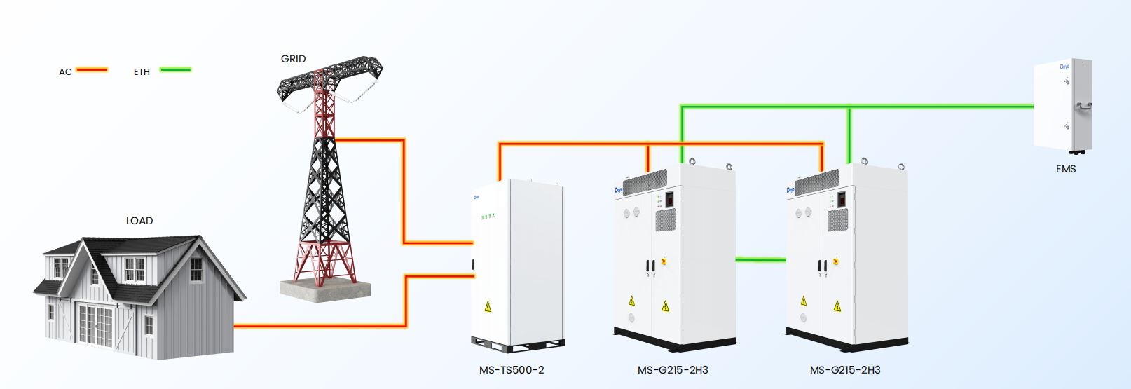
This is where the "one platform" claim earns its keep. Adding a diesel generator or switching from pure on-grid to a backup-capable design doesn't require a different EMS or a different battery cabinet — only the STS and the wiring topology change, while the EMS-PCS-BMS coordination logic inside each MS-G215 unit stays identical across every configuration in the catalog.
What Integration Actually Buys the Project
The practical payoff of unifying EMS, PCS, BMS, and STS shows up less in any single spec and more in what doesn't need separate commissioning: one communication protocol between battery and inverter, one control loop for SOC balancing and peak shaving, and one vendor accountable for the numbers on the datasheet. For an integrator scoping a 2MW industrial park deployment, that reduces the system down to a small set of decisions — how many MS-G215/GS215 units, whether an STS is needed, and how many EMS units the LC count requires — rather than a custom integration project between four separate suppliers. This is exactly the demand-charge-reduction scenario covered in the industrial and commercial parks peak-shaving solution.








3+ Branch Offices
1+ Factory
Required fields are marked


Copyright @ Hangzhou Seetek New Energy Sci-tech Co., LtD. All rights reserved Solar Energy Storage Solution Solar Energy Storage Products Supplier
